
A 4 mm vertical wall shadows about 1.2 mm of the floor beside it. That one line from an LDS design rule sheet explains most of what goes wrong when an LDS antenna is treated as a part to be added at the end.
LDS stands for Laser Direct Structuring. The antenna is not a component. It is a copper pattern plated straight onto the plastic case, so the case itself carries the antenna. In a small connected product, a wearable above all, that buys the three things an antenna wants and a circuit board cannot give it: length, height above the board and the battery, and clear space.
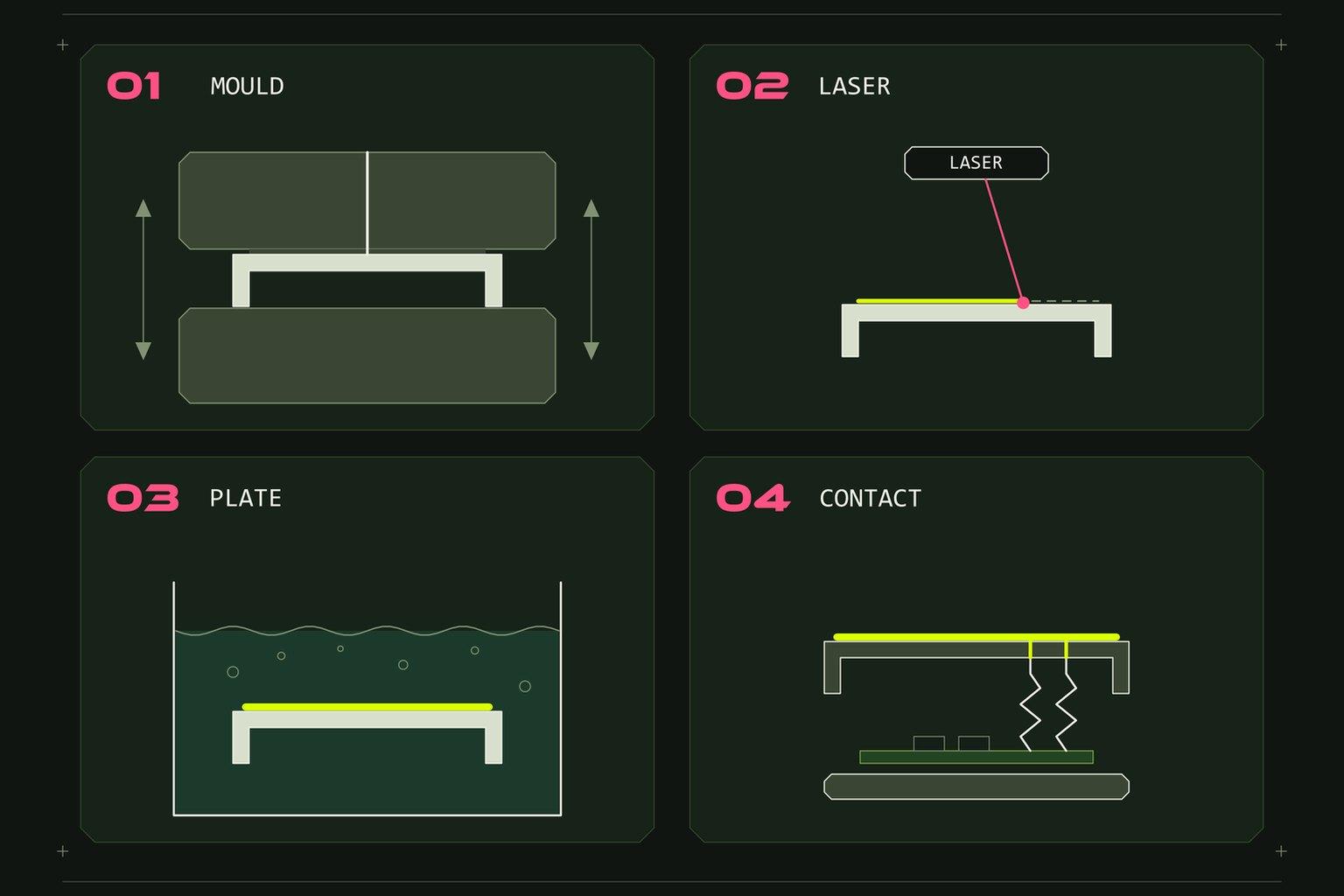
Four steps, one of them a mould
First, the case part is injection moulded from a plastic with a laser-activated additive mixed in. For a wearable case that is usually an LDS-grade polycarbonate. It looks and feels like normal case plastic.
Second, a laser draws the antenna pattern on the 3D surface. Where the beam lands it roughens the plastic and switches on the additive.
Third, the part goes through a plating bath. Metal grows only where the laser drew: 8 to 12 microns of copper, then 2 to 4 microns of nickel to protect it, with gold on the contact pads.
Fourth, spring contacts on the circuit board press against pads in the pattern when the case is closed. The matching components sit next to them on the board.
That is the whole process. Notice where the cost of a change sits. The mould is steel. The pattern is a laser program. As long as the plastic part and the contact positions stay the same, changing the antenna means changing a file, not cutting a new tool.
The laser has to see it
A laser is light, and light is blocked by anything in its way. The beam arrives from above and tilts at most 15 degrees from vertical, so the pattern cannot go anywhere the beam cannot reach.
This is where the wall comes in. A vertical wall shadows the floor next to it, and the taller the wall, the wider the shadow. So a step or a pocket that carries a pattern, or sits beside one, gets sloped walls: 30 degrees or more. An industrial designer who draws a crisp vertical-walled antenna pocket has drawn a pocket whose walls cannot be plated.
None of this hurts the antenna. It changes the shape of the part and the area you can use, which is why it has to be known before the enclosure is styled and not after the tool is ordered.
Rules small enough to forget
The numbers we draw to are not demanding. A minimum track of 0.3 mm. A minimum gap of 0.5 mm. Every corner of the pattern rounded to 0.3 mm or more. The pattern kept 0.2 mm in from any edge of the plastic.
Antenna tracks are usually far wider than the minimum, so the electrical design rarely fights these rules. The corners are the one people miss. A pattern drawn with square corners in the RF tool has to come back with fillets before it can be made.
Two rules belong to the enclosure and not to the pattern. The antenna zone carries no metal, and no conductive paint or coating either. A metallic finish over the antenna detunes it or shields it, and that holds for any antenna type. And the battery does not sit under the pattern. A lithium pouch cell is a sheet of metal; whatever antenna you fit, the battery is part of it.
What moves onto the board
An LDS antenna takes parts off the bill of materials and puts requirements onto the layout. The board needs pads where the spring contacts land. It needs a copper-free strip at the antenna end. It needs a matching network at each feed, and a test point on every feed, because an antenna you cannot measure is an antenna you cannot tune.
The mechanical side has to hold those contacts in place too. The case closes, the contacts compress, and the pattern, the board and the contact positions all have to land on each other within the tolerance of three different processes. That is one drawing set, kept by one team, or it is an argument between three.
When we would not use it
LDS is not the answer to every antenna. At 2.4 GHz a chip antenna on the board is fine for Bluetooth, and we leave it there. On a board with room to spare, a printed trace costs nothing. For a flat inner wall, a flexible printed antenna glued inside the cover uses the case in the same way with cheaper tooling; against it stand a flat film on a curved wall, a placement tolerance set by a fixture, and one more assembly step. We would compare the two on fit, repeatability and measured performance.
Where LDS earns its place is the product that is small, curved, and has to carry low-band cellular or GPS. A whole wave at 750 MHz is 400 mm and a wrist device is about 40 mm. In that product the case is the only place left with any length in it.
What the antenna asks, in order
Decide the bands. Give the antenna its zone on the case. Place the battery clear of it. Draw the board with contacts, matching and test points. Slope the walls the laser has to reach. Then style the enclosure around what is left, and measure the result in the closed case with the battery fitted.
We do LDS antenna design, the enclosure in Fusion 360, the DFM for injection moulding and the LDS manufacturing as one job, so if a product of yours needs an antenna on the case, send us the enclosure concept while it can still change.