
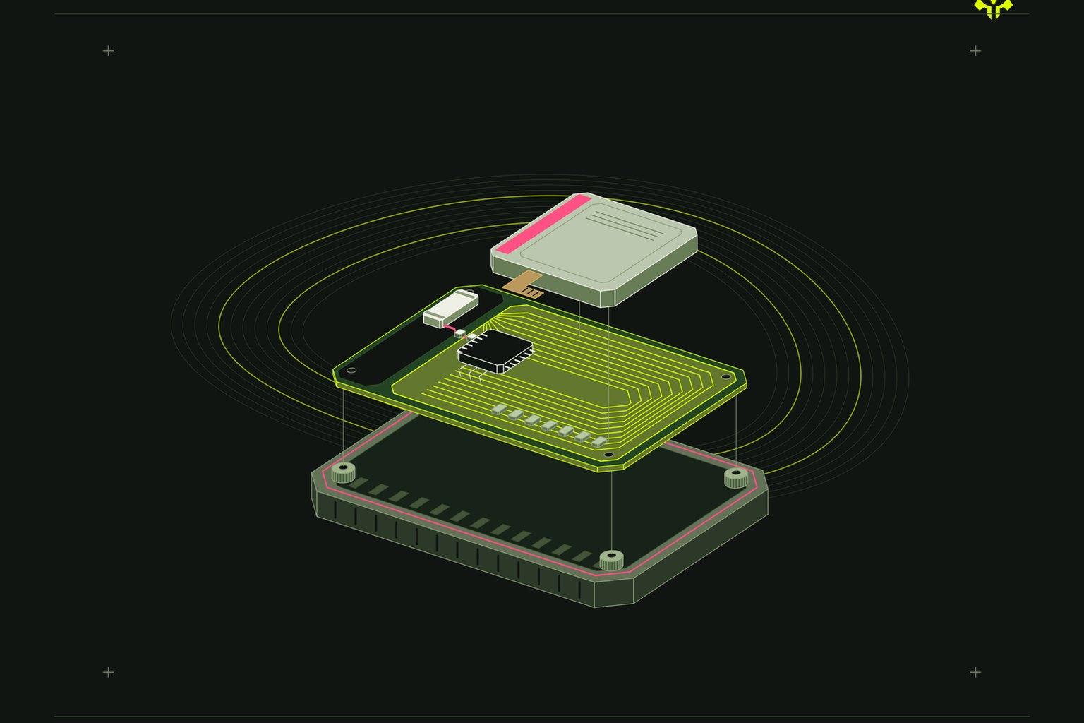
Six decibels costs you half your range. Twelve costs three quarters of it. Those are the numbers a chip antenna quietly takes back when the copper it sits on is smaller than the copper in the datasheet, and the datasheet almost always used more. Manufacturers characterise these parts on evaluation boards that are 40 by 40 mm or larger. A wearable main board is often 22 by 14 mm with a battery on top of it. Same part number, same matching network, a fraction of the performance, and nothing in the BOM records the loss.
The part you bought is not the thing that radiates
On a small product the antenna element is mostly a coupling structure. The currents it excites run on the ground plane, and the ground plane is what actually puts energy into the room. That is why the shape of your copper pour matters more than the brand of the antenna.
Wavelength is not negotiable. A quarter wave at 2.4 GHz is roughly 31 mm in air and shorter on FR4. At 868 MHz it is about 86 mm. A 30 mm board cannot be a quarter wave at 868 MHz no matter which component you solder onto the end of it, so a LoRa sensor the size of a matchbox is going to be an inefficient radiator or it is going to have something sticking out of it. Those are the options. Deciding which one early is a design decision; discovering it in week twelve is a respin.
So the real question is not chip against trace against external. It is how much contiguous ground plane the enclosure lets you keep, and in which dimension.
What we would actually choose
If the board has room, a printed inverted-F costs nothing in the BOM, holds its tuning across production far better than most people expect, and is the easiest thing in the world to reproduce on rev B. It costs board area and one tuning cycle. We reach for it first at 2.4 GHz whenever there is a ground plane at least a quarter wave long in one direction.
If area is tight but the ground is still one clean piece, a ceramic chip antenna and a three component pi network is a reasonable trade. Be honest about what it costs, though. The keep-out zone is still board area. You did not save space, you moved it, and you added a part that has to be tuned on the real assembly.
External wins in the cases people keep trying to argue their way out of. A metal enclosure. Sub-GHz. A device worn against a wrist or held in a fist. Anything that has to see the sky. Aluminium is a fine place to hide a battery and a terrible place to hide a GNSS antenna, which is the sort of thing that has to be settled while the frame is still a Fusion 360 model and the mount can still move.
Here is the position a lot of engineers will argue with. For a first product we would take the pre-certified radio module, accept the higher unit cost, and lay the board out exactly as the module vendor's reference design says, including their ground and keep-out. Discrete radio designs are cheaper per unit and we do them. But a first product does not have the schedule to absorb a full intentional radiator test failure, and modular approval only carries across if you use an antenna of the type and gain the grant covers. Change the antenna, or starve the module's ground plane, and you have quietly become the party responsible for the whole radio certification.
The keep-out is a mechanical requirement, not a layout note
No copper in the keep-out. Also no battery, no shield can, no speaker magnet, no metal bracket, no spring contact, no metallised paint on the inside of the housing, and no flex cable routed across it because it was the shortest path. A lithium pouch cell is a sheet of aluminium with a chemical filling. It behaves like a sheet of aluminium.
Plastic counts too. A 2 mm polycarbonate wall or a rubber overmould loads the antenna and pulls resonance down, typically by tens of megahertz, which is enough to walk a 2.4 GHz design off the top of the band. That is why the matching network gets tuned on a fully assembled unit with the case closed and the battery fitted, never on a bare board on a bench with a lab supply clipped to it.
We put the antenna keep-out into the CAD model as a 3D body, same as a screw boss or a connector envelope, and we review it in the mechanical review before anyone routes the board. A printed mock-up with a dummy cell taped in place answers the question in an afternoon. We would rather see an ugly print this week than a beautiful render next month.
Measure it, and measure it properly
Return loss is the easy number and the misleading one. S11 below -10 dB is the usual bar, and a 50 ohm resistor will beat that bar while radiating nothing at all. Match tells you power went in. Efficiency tells you power came out. They are not the same measurement.
Use a VNA, calibrate at the end of the cable, and feed the board through a short semi-rigid pigtail with a ferrite or a sleeve balun on it, or you will spend a day carefully tuning your coax. Then check the thing you actually care about: RSSI or packet error rate at a fixed distance, in the real housing, with the real battery, held the way a person holds it. A spectrum analyser will also tell you whether your radiated spurious emissions are anywhere near the limit line before you pay a lab to tell you the same thing more expensively.
And do not let a chatbot size your matching network. It will give you component values in a confident tone whether or not they are right, it does not know the errata or the app note for your module, and it cannot measure anything. A radio review is a VNA, a spectrum analyser and a real enclosure.
Certification is a design input
Failing radiated emissions is not fixed with a sticker. It is ground planes, filtering, cable routing and shielding, which means a respin and a new lab booking, and lab slots are booked weeks out. Pre-compliance while the design can still move is cheaper than any of that.
The cost of a change goes up roughly tenfold at every stage. On the antenna that curve is unusually steep, because the fix is often mechanical and mechanical fixes arrive after tooling.
If you are choosing between a chip, a trace and an external antenna right now, send us the board outline and the enclosure model and we will give you a second opinion.