
A 50 ohm resistor has a perfect match and radiates nothing. Keep that in mind the next time somebody shows you a return loss plot and tells you the antenna works.
There are two questions hiding inside "does the antenna work". Did the power go in? Did it come out as radio waves? The first is cheap to measure and flattering. The second is the one your product lives on, and a datasheet cannot answer it for you.
Whose board was that?
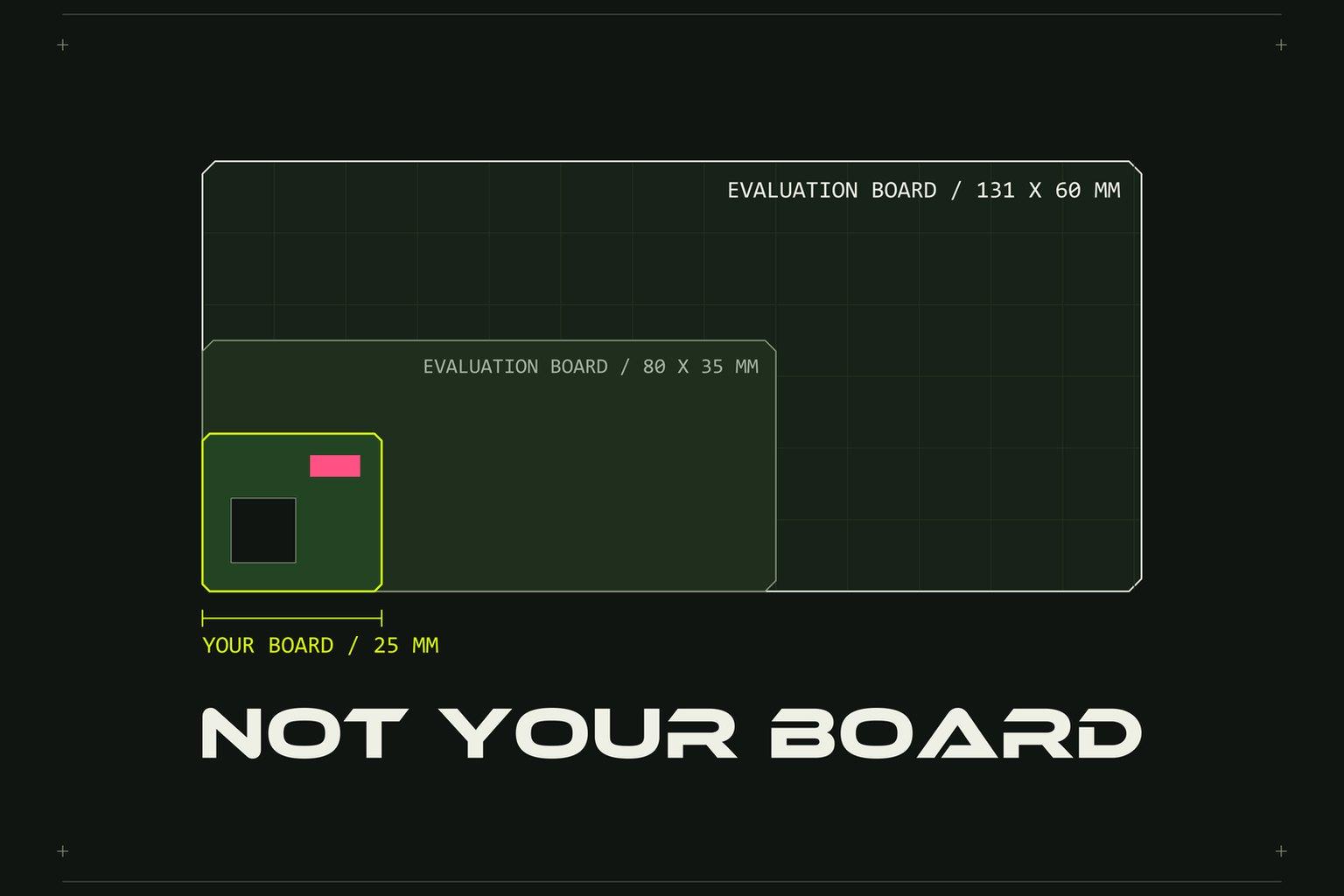
On a small product the antenna part is not what radiates. The board, the battery and the case radiate together, and the part only feeds them. A chip antenna's efficiency figure was therefore measured on something: the vendor's evaluation board. The published boards for two common parts are 80 x 35 mm and 131 x 60 mm.
Now look at your own product. A board 25 mm long. A lithium pouch cell under it, which electrically is a sheet of metal. A plastic wall a couple of millimetres from the part. Perhaps a wrist on the other side of that wall, and a wrist costs about 4 to 6 dB whatever the antenna type.
The figure on the datasheet is true. It is just somebody else's board.
Match is necessary. It is not sufficient.
Matching is the part most teams do get to. A network of small capacitors and inductors next to the feed reduces the power bounced back at the antenna connection. The usual bar is less than 10 % reflected, which is the same thing as S11 below -10 dB.
Matching corrects the frequency shift that nearby plastic and metal cause. It cannot give back the efficiency that the metal costs. And it only means anything on the real assembly: case closed, battery fitted, held or worn the way the product will be. A match tuned on a bare board on a bench describes a product nobody will ever use.
It also needs somewhere to happen. Boards we review often arrive with no tunable matching network on the cellular feed and no test point on any feed. Add ground copper running through the antenna's marked clear area and feed traces that work out nearer 30 ohm than 50, and there is nothing left to tune and no way to measure the result.
The decibels are the product
3 dB of antenna loss is half the power gone. 10 dB is nine tenths. A 50 % efficient antenna is -3 dB and a 5 % one is -13 dB. In open space, 6 dB less roughly halves the distance.
For GPS, the signal reaches the ground at about -130 dBm, and antenna loss comes straight off the margin between that and the receiver's limit. For cellular, a weak antenna keeps the modem at full power and retrying, so the loss shows up in battery life too.
Then comes the test you cannot skip. Before a cellular device may go on a network, the operator tests the whole device, not the module, for total radiated power and total isotropic sensitivity. TRP is how much power really leaves the product. TIS is how weak a signal the product can still hear. Each band has a minimum. Pass or fail.
Four numbers to agree before the design starts
This is where we take a position that is easy to argue with. We will not promise an efficiency figure at the start of an antenna design, and we think nobody honestly can. What can be promised is a programme of prototypes and measurements, with the thresholds written down first.
One. Match: less than 10 % of the power reflected across every required band, measured in the closed case with the battery fitted.
Two. Total efficiency per band, measured in a chamber, in free space and, for a wearable, on a wrist phantom. Reported as the band average and the worst frequency, because an average hides the edge of the band where the device will fail.
Three. GPS performance within a stated margin of a named reference receiver. Same sky, same session.
Four. TRP and TIS per band, compared with the chosen operators' minimums before the device is submitted to them.
Each number has a floor agreed in advance, and a decision attached to missing it: corrective work, a dropped band, or a change to the product. That conversation is far cheaper in week one than in a certification lab.
What changes when the numbers come first
The product gets designed in a different order. If the low LTE bands are on the list, the arithmetic is on the table from day one: a quarter wave at 750 MHz is 100 mm and the product may be 40 mm long. That sends the antenna off the board and onto the case, as an LDS pattern plated on the plastic, and it moves the battery out from under it. Those are enclosure decisions. They are free on a sketch and very expensive after tooling.
It also changes what goes on the board. Contact pads, a matching network and a test point on every feed, and clear space that stays clear in the layout and not only in the datasheet's drawing.
If you have a board and an enclosure and a datasheet that says it should all work, send us the files and the band list, and we will tell you what we would measure first.