
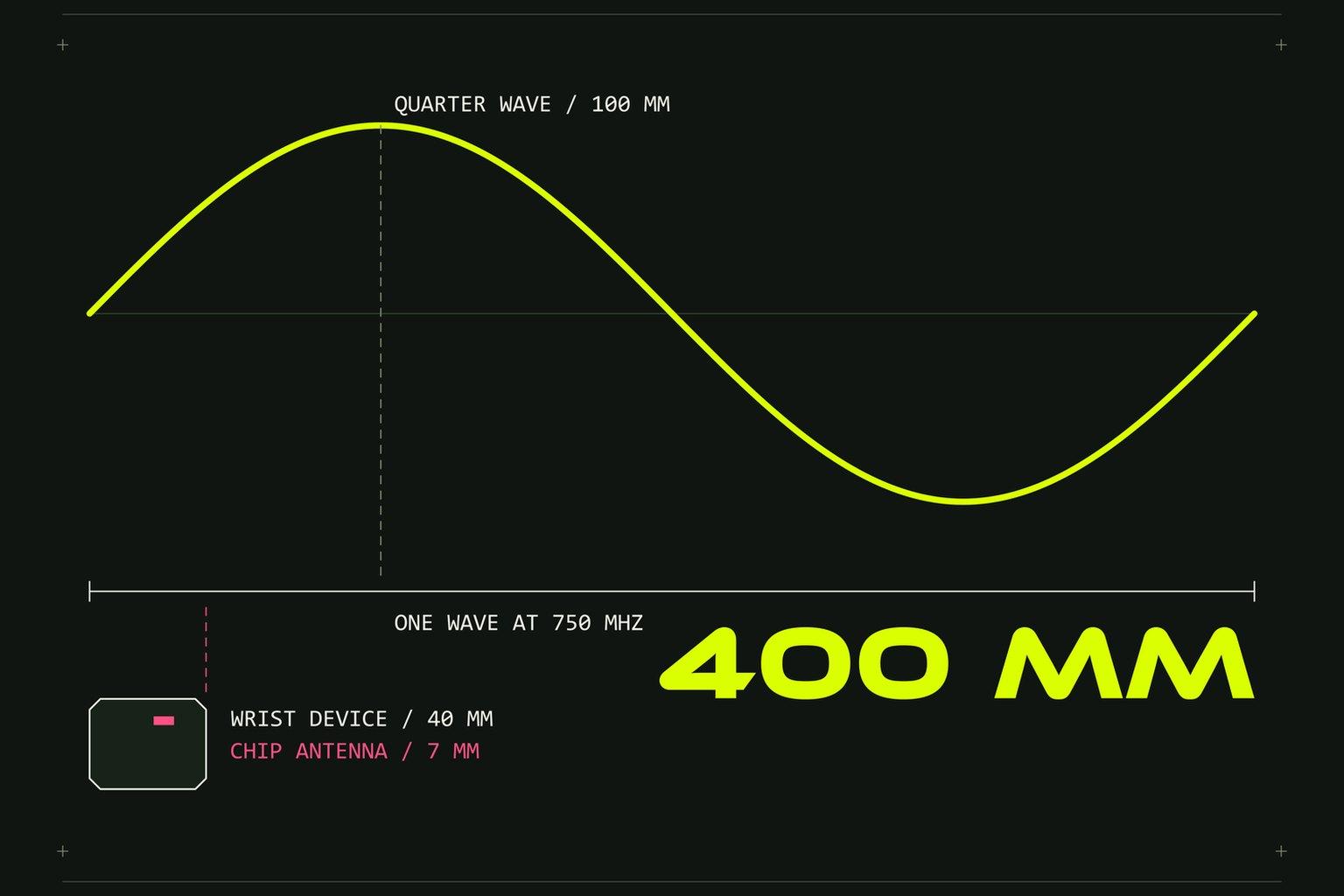
One whole radio wave at 750 MHz is 400 mm long. A wrist-worn device is about 40 mm long. Everything below follows from those two numbers, and no component on the bill of materials changes either of them.
Here is a pattern we have seen and expect to see again. A smart wearable comes to us after another team has designed it. It has an LTE-M modem, GPS and Bluetooth. Each radio has its own chip antenna, soldered to a small board with the battery directly under it. The low LTE bands were never going to work there.
That is not a layout fault a respin fixes. It is the size of the product against the wavelength. The fix is a redesign of the battery, the board outline and the enclosure, after the first design has already been paid for.
The arithmetic nobody ran
A simple antenna is about a quarter of a wavelength long. At 750 MHz, LTE band 28, that is 100 mm. In band 20 it is 91 mm. In band 8 it is 81 mm. Compare GPS at 1575 MHz, where a quarter wave is 48 mm, and Bluetooth at 2.4 GHz, where it is 31 mm.
Smaller antennas work. They pay for it in efficiency and bandwidth, whatever their shape, and the price climbs as the product shrinks. Length, height above the board and battery, and clear space are the only levers. A chip antenna about 7 mm long, sitting about 1 mm above the board next to a lithium pouch cell, gets almost none of them. A pouch cell is a sheet of metal. Whatever antenna you fit, the battery is part of it.
The datasheet was measured on a board you do not have
On a small product the antenna part is not the thing that radiates. The board, the battery and the case radiate together, and the part only feeds them. So a chip antenna's datasheet efficiency belongs to the vendor's evaluation board. The published boards for two common parts are 80 x 35 mm and 131 x 60 mm. Solder the same part onto a board 25 mm long and the number on page one does not come with it.
Nothing in the BOM records that loss. The part number is right. The matching values are copied from the reference design. The efficiency is a fraction of the quoted figure, and it stays invisible until somebody measures the assembled device, or an operator's test lab does it for you.
What the lost decibels cost
3 dB of antenna loss is half the power gone. 10 dB is nine tenths. A 50 % efficient antenna is -3 dB, and a 5 % one is -13 dB. In open space, 6 dB less roughly halves the distance to the tower.
GPS has it worse, because it only listens. Satellite signals reach the ground at about -130 dBm, and antenna loss comes straight off the margin between that and the receiver's limit. Then the product goes onto a wrist, and the body takes about 4 to 6 dB more, whatever the antenna type.
There is a battery cost as well. A weak antenna keeps the modem transmitting at full power and retrying.
And there is a gate at the end. Operators test the whole device for total radiated power and total isotropic sensitivity before it may go on their network. Pass or fail. The antenna is what is being tested.
Where the antenna has to go instead
If the board is too small to be the antenna, use the case. That is what an LDS antenna is. LDS stands for Laser Direct Structuring. The case part is moulded from a plastic with a laser-activated additive mixed in, a laser draws the antenna pattern on its surface, and a plating bath grows copper only where the laser drew. Spring contacts on the board press against the pattern when the case closes.
The pattern can run along an end face and down a side. It sits higher above the board and the battery than any soldered part can. It follows curves. Changing it is a new laser program, not a new mould, as long as the plastic part and the contact positions stay the same.
It is not magic. A 40 mm case is still a tenth of a wave in the 700 MHz bands, and an antenna in it is still a small antenna with a small antenna's efficiency. What LDS does is take every millimetre of length and height the product has, which a chip on the board cannot. Whether that is enough is a number you measure, in the closed case with the battery fitted, against a threshold agreed before the design starts.
One place we would argue with ourselves: Bluetooth. At 2.4 GHz a chip antenna is fine, and we keep it there. Our position is not that chip antennas are bad. It is that low-band cellular does not fit in one, in a product this size.
The order of decisions
The expensive part of that pattern is not the antenna. It is the order. The usual order is the enclosure first, then the biggest battery that fits, then a board shrunk into whatever is left, and the antenna picked last, from a catalogue. Each of those decisions is reasonable on its own.
Run it the other way. Bands first, because every band you drop makes the antenna easier. Then the antenna's zone on the case. Then the battery, sized and placed so that it does not sit under the pattern. Then the board outline, with a copper-free strip at the antenna end, contact pads, a matching network and a test point on every feed. The enclosure comes out of that work, not before it.
An antenna that needs a different battery is a change to the whole product. It belongs on the first sketch, where changes are free.
If you are planning a wearable or a tracker with LTE-M or GPS in it, send us the band list and the enclosure concept before the board is drawn, and we will tell you where the antenna can live.